Hanmatek DOS1104
How to Use Hanmatek DOS1104 Portable 4-Channel Oscilloscope (110MHz)1️⃣ What is a 4-Channel Portable Oscilloscope?
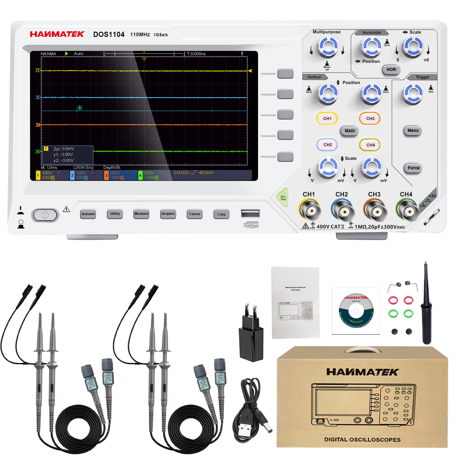
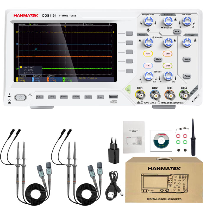
The Hanmatek DOS1104 is a portable digital oscilloscope with four independent input channels, designed to capture and analyze multiple electrical signals simultaneously. Key features include:
- 4 signal channels – observe multiple signals in real time.
- 110MHz bandwidth – suitable for medium- to high-frequency signal analysis.
- Portable design – compact and easy to transport for field diagnostics.
- Advanced triggering and analysis tools – stabilize complex signals and perform automatic measurements.
Purpose: The DOS1104 is widely used in electronics development, industrial maintenance, power system testing, and education, where engineers need to compare and analyze several signals at once.
2️⃣ How it Works
The oscilloscope measures voltage as a function of time and displays the waveform visually:
- Signal input: Probes connect the oscilloscope channels to the test points.
- Signal conditioning: The input stage applies attenuation, amplification, and coupling (AC/DC).
- Analog-to-digital conversion: Signals are sampled at high speed and converted into digital data.
- Waveform display: The processor renders waveforms on the screen with time and voltage scales.
- Trigger system: Stabilizes periodic signals so they appear steady.
- Analysis tools: Automatic measurements, cursors, and waveform math help interpret signal behavior.
Tip: Multi-channel observation allows you to compare signal timing relationships, such as input vs. output or phase differences.
3️⃣ Key Specifications Explained
- Channels: 4 independent input channels for measuring multiple signals simultaneously.
- Bandwidth: 110 MHz maximum signal frequency.
- Sampling Rate: Up to 1 GSa/s for accurate waveform capture.
- Display: Color LCD with waveform visualization.
- Trigger Modes: Supports edge, pulse, slope, and video triggers.
- Measurement Functions: Measures voltage, frequency, period, RMS, and rise/fall time.
- Waveform Storage: Internal memory stores multiple waveform captures.
- Input Coupling: Selectable AC, DC, or GND.
- Safety: Rated CAT II 600V.
Why it matters:
- Four channels enable multi-signal comparison and system-level diagnostics.
- High sampling rate ensures waveform accuracy and detailed transient capture.
- Advanced triggering allows stable display of complex or intermittent signals.
4️⃣ Typical Use Cases
- Multi-stage circuit debugging – analyze input, intermediate, and output signals simultaneously.
- Power electronics testing – monitor control signals, switching waveforms, and load response.
- Motor drive and inverter diagnostics – compare multiple phase signals.
- Embedded system development – verify timing between digital control lines.
- Field service and maintenance – portable design enables on-site measurements.
Example scenario:An engineer troubleshooting a switching power converter monitors gate drive, input voltage, output voltage, and feedback signal on four channels simultaneously. This reveals a timing delay causing instability.
5️⃣ How to Use the Device (Step-by-Step)
- Safety PreparationEnsure probes are properly rated.Use appropriate personal protective equipment.
- Power OnTurn on the oscilloscope and allow initialization.Perform calibration if required.
- Connect ProbesAttach probes to channels CH1–CH4.Connect ground leads securely.
- Set Input CouplingChoose AC for ripple/noise analysis.Choose DC for full signal measurement.
- Adjust Vertical Scale (Voltage)Set volts/div for each channel independently.
- Adjust Horizontal Scale (Time)Set time/div to view one or more waveform cycles.
- Configure TriggerSelect trigger source channel.Set trigger level and mode for stable waveform display.
- Measure SignalsEnable automatic measurements.Use cursors for manual analysis.Apply math functions (CH1–CH2, etc.).
- Capture and Store DataFreeze waveform using single capture.Save waveform or screenshot to internal memory or USB.
- Compare Multiple Signals
- Use different colors and scales for each channel.
- Align signals in time for phase analysis.
Pro tip: Use one channel as a trigger reference and others for comparison to maintain stable multi-signal display.
6️⃣ Common Problems & Troubleshooting
- No waveform visible: Channel may be disabled or probe disconnected. Enable the channel and check the connection.
- Unstable waveform: Trigger settings may be incorrect. Adjust trigger level or mode.
- Overlapping signals hard to read: Vertical scale may not match. Adjust volts/div for each channel.
- Signal clipped: Voltage exceeds display range. Increase vertical scale.
- Unable to store waveform: Memory full or USB issue. Clear memory or reconnect USB.
Safety note: Never exceed the maximum input voltage rating. Always verify grounding before measurement.
7️⃣ Comparison with Alternatives
- Hantek DOS1104: 4 channels, 110 MHz bandwidth, portable. Best for multi-signal analysis in field or lab.
- 2-channel oscilloscope: 2 channels, 50–100 MHz bandwidth, portable. Best for basic signal observation.
- High-end lab oscilloscope: 4–8 channels, 200+ MHz bandwidth, bench-top. Best for advanced research and high-speed systems.
Advantage: The DOS1104 combines multi-channel capability, portability, and strong performance, making it suitable for both lab and field diagnostics.