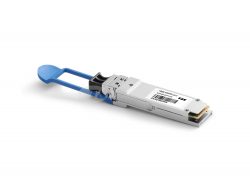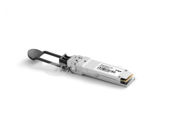
QSFP+ 40G SR4 400M
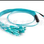
The QSFP+ 40G-SR4-400m module is a highly integrated 4x10G transceiver focused on reach, bandwidth, density and cost for high port-count 40G systems, and client-side 40G interfaces. Each lane can operate at 10.3125Gbps up to 300m using OM3 fiber or 400m using OM4 fiber. These modules are designed to operate over multimode fiber systems using a nominal wavelength of 850nm. The electrical interface uses a 38-contact edge type connector. The optical interface uses a 12-fiber MTP/MPO connector.
Features of QSFP+ 40G SR4 400m
l 4 channels full-duplex transceiver modules
l Transmission data rate up to 10.5Gbps per channel
l 4 channels 850nm VCSEL array
l 4 channels PIN photo detector array
l Hot-pluggable QSFP form factor
l Maximum link length of 300m on OM3 Multimode Fiber(MMF) and 400m on OM4 MMF
l Single 1X12 MPO connector receptacle
l Hot-pluggable electrical interface
l 0–70°C operating temp
l Low power consumption < 1.5W
l RoHS6 compliant (lead-free)
Applications of QSFP+ 40G SR4 400m
l 40G Ethernet and OTU3
l Datacom/Telecom switch & router connections
l Data Aggregation and Backplane Applications
l Proprietary Protocol and Density Applications
l Infiniband transmission at 4ch SDR, DDR and QDR
Specifications of QSFP+ 40G SR4 400m
Optical Transmitter Performance|Optical Receiver Performance|Recommended Operating Environment
Parameter
Symbol
Min
Typical
Max
Unit
Signaling Speed per Lane
10.5
Gb/s
Center Wavelength
λC
840
850
860
nm
RMS spectral width
∆λ
–
0.4
nm
Average Launch Power per Lane
TXPx
-7.5
0.5
dBm
Transmit OMA per Lane
TxOMA
-2.5
3
dBm
Difference in launch power between any two lanes (OMA)
DPx
4
dB
Peak Power per Lane
PPx
4
dBm
Launch Power [OMA] minus TDP per Lane
P-TDP
-6.5
dBm
Extinction Ratio
ER
3
dB
Optical Return Loss Tolerance
ORL
12
dB
Encircled Flux
FLX
> 86% at 19 um
< 30% at 4.5 um
dBm
Average launch power of OFF transmitter, each lane
-30
dBm
Transmitter eye mask definition {X1, X2, X3, Y1, Y2, Y3}
0.23, 0.34, 0.43, 0.27, 0.35, 0.4
Pin Descriptions of QSFP+ 40G SR4 400m
Pin Definition of QSFP+ 40G SR4 400m
Pin
Symbol
Name/Description
1
GND
Ground
2
Tx2n
Transmitter Inverted Data Input
3
Tx2p
Transmitter Non-Inverted Data Input
4
GND
Ground
5
Tx4n
Transmitter Inverted Data Input
6
Tx4p
Transmitter Non-Inverted Data Input
7
GND
Ground
8
ModSelL
Module Select
9
ResetL
Module Reset
10
Vcc Rx
+3.3 V Power supply receiver
11
SCL
2-wire serial interface clock
12
SDA
2-wire serial interface data
13
GND
Ground
14
Rx3p
Receiver Non-Inverted Data Output
15
Rx3n
Receiver Inverted Data Output
16
GND
Ground
17
Rx1p
Receiver Non-Inverted Data Output
18
Rx1n
Receiver Inverted Data Output
19
GND
Ground
20
GND
Ground
21
Rx2n
Receiver Inverted Data Output
22
Rx2p
Receiver Non-Inverted Data Output
23
GND
Ground
24
Rx4n
Receiver Inverted Data Output
25
Rx4p
Receiver Non-Inverted Data Output
26
GND
Ground
27
ModPrsL
Module Present
28
IntL
Interrupt
29
Vcc Tx
+3.3 V Power supply transmitter
30
Vcc1
+3.3 V Power Supply
31
LPMode
Low Power Mode
32
GND
Ground
33
Tx3p
Transmitter Non-Inverted Data Input
34
Tx3n
Transmitter Inverted Data Input
35
GND
Ground
36
Tx1p
Transmitter Non-Inverted Data Input
37
Tx1n
Transmitter Inverted Data Input
38
GND
Ground
Important Notice of QSFP+ 40G SR4 400m
Performance figures, data and any illustrative material provided in this data sheet are typical and must be specifically confirmed in writing by T&S before they become applicable to any particular order or contract. In accordance with the T&S policy of continuous improvement specifications may change without notice.
The publication of information in this data sheet does not imply freedom from patent or other protective rights of T&S or others. Further details are available from any T&S sales representative.