HSG Engineering Hydraulic Cylinders
What is HSG Engineering Hydraulic Cylinder?
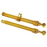
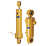
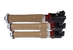
HSG type engineering hydraulic cylinder is a double-acting single-rod piston type hydraulic cylinder. It has the characteristics of simple structure, reliable operation, convenient assembly and disassembly, easy maintenance, buffering device and various connection methods. Mainly used in construction machinery, transportation, ships, lifting machinery, mining, machinery.
Advantages of HSG Engineering Hydraulic Cylinder:
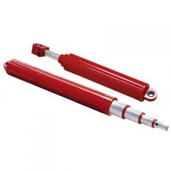
The HSG series engineering hydraulic cylinder is a double-acting single-piston rod hydraulic cylinder; the mounting method is mostly ear-ring type. There are three types of external connection: internal key connection and flange connection according to the connection method of the cylinder head and the cylinder. Engineering hydraulic cylinders are mainly used in hydraulic systems such as construction machinery, heavy machinery, lifting machinery and mining machinery.
Product Description
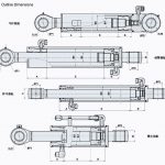
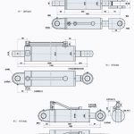
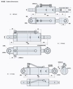
Front and Rear Earrings Installation Features of HSG Engineering Hydraulic Cylinder
The tail single earring is suitable for the single earring installation condition required for the path condition or structural design of the piston rod to be along the path of the same motion plane when the piston rod is moving along the same motion plane; It is possible to install the tail and rod end spherical bearings at this time, but pay attention to the pressure load that the spherical bearing is allowed to bear.
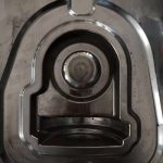
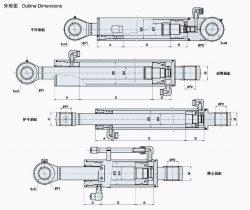
HSG double-acting single-rod piston type hydraulic cylinder is mainly composed of a cylinder tube, a piston, a piston rod, a cylinder head, a cylinder bottom, a piston rod head and related auxiliary devices. The piston divides the cylinder into two left and right chambers. By means of the action of the pressure oil, the cylinder reciprocates. In order to improve its working effect, a sealing ring is arranged on the piston to eliminate internal leakage. Where the piston rod passes through the cylinder head, due to the existence of the gap, the external leakage phenomenon is easy to occur, and the dust can enter the cylinder through the gap, so the sealing device and the dustproof factor are set. At the same time, in order to eliminate the influence of the eccentric load on the piston operation All hydraulic cylinders must be placed at the protruding end of the piston rod, and a guiding sleeve of a considerable length is provided. In addition, when the piston moves at a faster speed, the mechanical collision between the piston and the cylinder bottom and the cylinder head is serious, so the hydraulic cylinder at both ends, a buffer reduction gear should be provided.
Model Coding:
Engineering_Hydraulic_Cylinders_Model_Coding.jpg
① Unit code
②Connecting type L: Screw K: Clasp F: Flange
③ Bore/Rod (mm)
④ Pressure E: 16MPa F: 20MPa G: 25MPa
⑤ Mounting
⑥ Connecting in rod
⑦ Oil port 1: Screw 2: Flange
⑧ Stroke (mm)
⑨ Mounting distance
Technical Specification:
Specifications: Mark* is for speed ratio 1.64 only.
Bore D
Φ
d
d1
R
b
L6
M2
L10
L5
L7
L2
2-M1
H1
Φ1
pressure
speed ratio
16
20
25
1.33
1.46
2(1.64)
32
42
48
16
18
*20
16/GE6ES
20
18
20
M14X1.5
40
40
50
245
M14X1.5
15
50
40
50
56
20
22
25
20/GE20ES
25
30
M16X1.6
50
30
65
255
65
50
65
68
25
28
32
30/GE30ES
35
40
M22X1.7
60
40
280
M18X1.5
75
63
78
80
83
32
35
45
M27X1.8
65
295
79
80
95
102
40
45
55
40/GE40ES
45
50
M33X1.9
80
50
70
347
M22X1.5
18
110
90
108
114
45
50
63
M36X2
90
66
357
100
118
127
50
55
70
50/GE50ES
60
65
M42X2
110
60
72
402
M27X2
20
110
130
133
140
55
63
80
M48X2
115
77
422
125
145
152
63
70
90
M52X2
140
78
452
140
164
168
70
80
100
60/GE60ES
70
75
M60X2
155
70
85
498
150
180
75
85
105
M64X2
160
75
92
513
M33X2
22
160
194
80
90
110
M68X2
170
80
100
533
180
219
90
100
125
70/GE70ES
80
85
M76X2
190
89
107
588
M42X2
24
200
245
100
110
140
80/GE80ES
95
90
95
M85X2
210
100
110
628
220
273
110
125
160
90/GE90ES
105
100
105
M95X2
220
110
120
658
25
250
299
125
140
180
100/GE100ES
120
110
120
M105X2
255
122
135
688
Bore D
rod
pressure 16Mpa
speed ratio
Pushing force(KN)
pull force(KN)
1.33
1.46
2(1.64)
speed ratio=1.33
speed ratio=1.46
speed ratio=2(1.64)
32
16
18
*20
12.9
9.0
8.8
*7.8
40
20
22
25
20.1
15.1
14.0
12.3
50
25
28
32
31.4
23.6
21.6
18.5
63
32
35
45
49.9
34.5
34.5
24.4
80
40
45
55
80.4
55.0
55.0
42.4
90
45
50
63
101.8
70.4
70.4
51.9
100
50
55
70
125.7
87.7
87.7
64.1
110
55
63
80
152.1
102.2
102.2
71.6
125
63
70
90
196.4
134.8
134.8
94.6
140
70
80
100
246.3
165.9
165.9
120.6
150
75
85
105
282.7
191.9
191.9
144.2
160
80
90
110
321.7
219.9
219.9
169.7
180
90
100
124
407.2
281.5
281.5
210.8
200
100
110
140
502.7
350.6
350.6
256.4
220
110
125
160
608.2
411.9
411.9
286.5
250
125
140
180
785.4
539.1
539.1
378.3
Mounting
Code
Mounting
Notice
1
single articulated clevis( with bush)
2
single articulated clevis( with oscillating bearing)
3
middle trunnion
Bore ≥80
4
front flange
Bore ≥80
5
middle flange
Bore ≥80
Piston rod connecting
Code
Mounting
Notice
1
outside screw
2
outside screw and articulated clevis( with bush)
3
outside screw and articulated clevis( with oscillating bearing)
4
one piece single articulated clevis( with bush)
5
one piece single articulated clevis( with oscillating bearing)
Specifications:
Mark* is for speed ratio 1.64 only.
Bore D
Φ
d
d1
R
b
L6
M2
L10
L5
L7
L2
2-M1
H1
Φ1
pressure
speed ratio
16
20
25
1.33
1.46
2(1.64)
32
42
48
16
18
*20
16/GE6ES
20
18
20
M14X1.5
40
40
50
245
M14X1.5
15
50
40
50
56
20
22
25
20/GE20ES
25
30
M16X1.6
50
30
65
255
65
50
65
68
25
28
32
30/GE30ES
35
40
M22X1.7
60
40
280
M18X1.5
75
63
78
80
83
32
35
45
M27X1.8
65
295
79
80
95
102
40
45
55
40/GE40ES
45
50
M33X1.9
80
50
70
347
M22X1.5
18
110
90
108
114
45
50
63
M36X2
90
66
357
100
118
127
50
55
70
50/GE50ES
60
65
M42X2
110
60
72
402
M27X2
20
110
130
133
140
55
63
80
M48X2
115
77
422
125
145
152
63
70
90
M52X2
140
78
452
140
164
168
70
80
100
60/GE60ES
70
75
M60X2
155
70
85
498
150
180
75
85
105
M64X2
160
75
92
513
M33X2
22
160
194
80
90
110
M68X2
170
80
100
533
180
219
90
100
125
70/GE70ES
80
85
M76X2
190
89
107
588
M42X2
24
200
245
100
110
140
80/GE80ES
95
90
95
M85X2
210
100
110
628
220
273
110
125
160
90/GE90ES
105
100
105
M95X2
220
110
120
658
25
250
299
125
140
180
100/GE100ES
120
110
120
M105X2
255
122
135
688
Bore D
rod
pressure 16Mpa
speed ratio
Pushing force(KN)
pull force(KN)
1.33
1.46
2(1.64)
speed ratio=1.33
speed ratio=1.46
speed ratio=2(1.64)
32
16
18
*20
12.9
9.0
8.8
*7.8
40
20
22
25
20.1
15.1
14.0
12.3
50
25
28
32
31.4
23.6
21.6
18.5
63
32
35
45
49.9
34.5
34.5
24.4
80
40
45
55
80.4
55.0
55.0
42.4
90
45
50
63
101.8
70.4
70.4
51.9
100
50
55
70
125.7
87.7
87.7
64.1
110
55
63
80
152.1
102.2
102.2
71.6
125
63
70
90
196.4
134.8
134.8
94.6
140
70
80
100
246.3
165.9
165.9
120.6
150
75
85
105
282.7
191.9
191.9
144.2
160
80
90
110
321.7
219.9
219.9
169.7
180
90
100
124
407.2
281.5
281.5
210.8
200
100
110
140
502.7
350.6
350.6
256.4
220
110
125
160
608.2
411.9
411.9
286.5
250
125
140
180
785.4
539.1
539.1
378.3
Mounting
Code
Mounting
Notice
1
single articulated clevis( with bush)
2
single articulated clevis( with oscillating bearing)
3
middle trunnion
Bore ≥80
4
front flange
Bore ≥80
5
middle flange
Bore ≥80
Piston rod connecting
Code
Mounting
Notice
1
outside screw
2
outside screw and articulated clevis( with bush)
3
outside screw and articulated clevis( with oscillating bearing)
4
one piece single articulated clevis( with bush)
5
one piece single articulated clevis( with oscillating bearing)
SIMILAR PRODUCTS