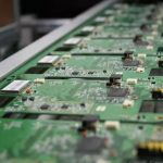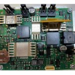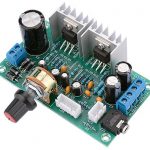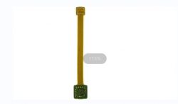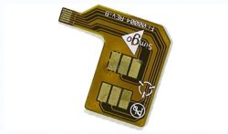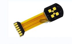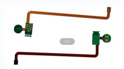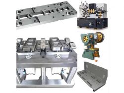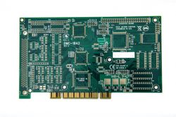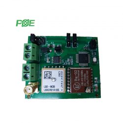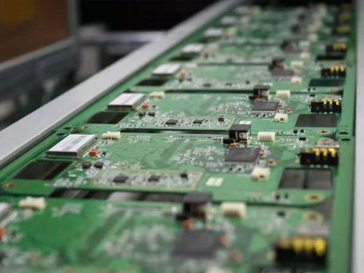
Instrument PCBA Board
When manufacturing plenty of PCB boards, it is impossible to solder parts by hand. You will need PCB instruments to complete this step, to make a bare board, and assemble all parts onto the printed circuit board. There are many issues to consider at each stage of the assembly process, to provide a perfect functional printed circuit board. As a professional PCB board manufacturer, HX Technology provides high-quality PCB instruments for customers.
Introduction to PCB Instrument
The basic instruments required for PCB assembly include:
Solder Paste Printing machine
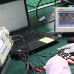
Solder Paste Inspection (SPI) machine
Glue Dispensing machine
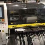
Pick-and-Place machine
Reflow Soldering machine
Wave Soldering machine (for through-hole components)
Automatic Optical Inspection (AOI) machine
In-Circuit Test (ICT) Fixture
Functional Validation Test (FVT) Fixture
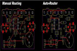
PCB Instrument’s Unified Design Environment Foundation
One of the most important keys to the success of any PCB design software is its ability to work with other tools. It can take a lot of your time and effort to force different tools to communicate with each other in the CAD program. On the other hand, tools that are designed to work together will save you a lot of trouble. Something as simple as having an easy-to-navigate user interface for compatible file formats (such as DWG files) can be helpful. If the design system consists of tools that are not initially created tools must be connected or translated, which adds time and complexity to the process. Each tool can use its own design data in its component model, netlist, file format, etc., and all of these tools must be mixed with other tools in some way. The problem can be worse in cases where tools from different systems are used. You may see misinterpretations of the data, or you may even discard some data altogether during transfer and conversion.